


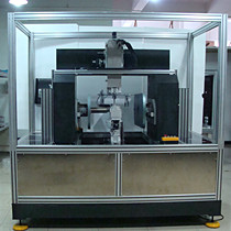
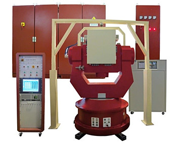
Custom Workstation for rapid, precise fiber optic coil winding for gyroscopes
Product Features
Technical Specification
I. Dominant ideas on design:
I.1 The operability, safety, stability, and maintainability of the equipment are taken into key consideration in the design of the whole structure and software of the equipment.
I.2 Relevant national standards and industrial standards are used for all contents involved in the structure and electrical design schemes;
I.3 All constituent parts of the equipment are the matured products by importing or from domestic well-known enterprises, and the selected enterprises have the qualification of certificate of quality system;
I.4 The manufacturer fully considers the actual situations of the equipment production site, increases communication with operators, and makes a feasible equipment plan to meet the use of the user.
II. Main Technical Parameters of the Equipment
II.1 Diameter range of winding fiber: φ0.10mm~φ0.30mm;
II.2 Maximum ring winding speed of the machine tool is not lower than 40 r/min;
II.3 The rotational position accuracy of the spindle is superior to 1°;
II.4 The radial run-out of the spindle is superior to 0.02 mm;
II.5 The effective winding displacement of the traverse shaft is not less than 60 mm;
II.6 The maximum movement speed of the traverse shaft is not lower than 80 mm/s;
II.7 The repeated positioning accuracy of the traverse shaft is superior to 0.01 mm;
II.8 The detection accuracy of length shall be not less than 0.1%;
II.9 The diameter of the fiber is accurate to 0.001 mm;
II.10 The set and control range of the tension is 5g~20g, and the control precision of the tension is superior to 1.5g; the tension is kept stable during startup and shutdown of the equipment, and the fluctuation is not higher than ±2 g;
II.11 The display resolution of the image observation system is not lower than 480P, the displayer is not smaller than 24 inch, and the amplification factor of the image observation system is not less than 40 times;
II.12 Product dimension: one single host occupies an area of not greater than 2900mmx1400mm;
II.13 Product weight: one single host weighs not greater than 5000 kg;
II.14 Product power: the power of one single host is not greater than 6 kw.
|
Technical Indexes of Custom
Workstation for fiber optic coil winding for gyroscopes |
||
| Model |
Unit |
Technical indexes |
| Specification |
|
Full-automatic |
| Type of machine |
|
Floor type |
| Maximum fiber diameter |
mm |
Φ0.5 |
| Power supply |
|
Three phases AC380V (10%), 50/60Hz |
| Power |
Kw |
〈6 |
| Weight |
kg |
≤[5000kg] |
| External dimension (length * width
* height) |
mm |
2520*1320*2350 |
| Number of spindles |
|
2 |
| Spindle motor |
W |
Two 2 KW AC servo motors |
| Highest spindle speed |
rpm |
60 |
| Spindle positioning accuracy |
Degree |
<1° |
| Maximum winding speed |
m/min |
≥10 |
| Rotational position accuracy of
the spindle |
Degree |
<1° |
| Radial run-out accuracy of the
spindle |
mm |
0.02 |
| Repeated positioning accuracy of
the traverse shaft |
mm |
0.005 |
| Winding displacement of left and
right units |
mm |
≥100 |
| Diameter of product ring |
mm |
≤200 |
| Groove width of product ring |
mm |
10--70 |
| Tension control range |
g |
5--30 |
| Tension error |
g |
<1.5 |
| Fluctuation of tension during
startup and shot-down |
g |
±2 |
| Reversing time |
s |
≤95 |
| Image amplification factor |
|
≥40 times |
| Image display resolution |
|
>480P |
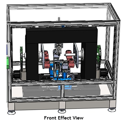
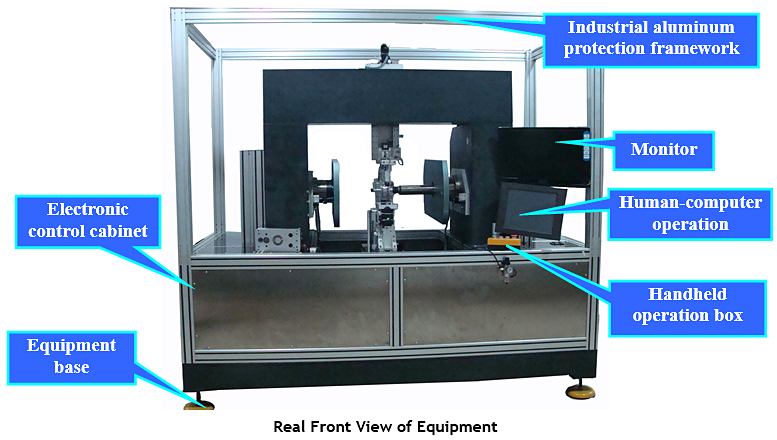
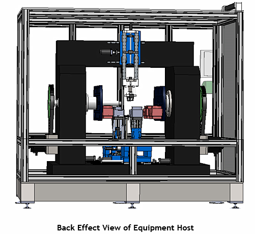
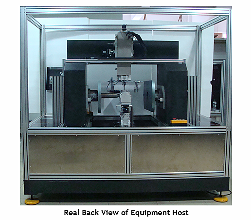
I. View of complete winding machine
II. Components of winding machine
The equipment is composed of the following parts: Base piece (equipment body), precise spindle system, full closed-loop tension control system and automatic feeding fiber system, automatic interleaving position system, the traversing and positioning device of fiber, precise wire laying and camera drive unit, and the control system, etc.
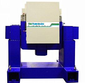
II.1 Base piece (equipment body): It consists of lathe bed, left and right spindle boxes and workbench. It is the fundamental component and mainly sustains the dead load of the equipment and dynamic load during operation of the equipment. Therefore, the component should have very high rigidity, and it is also the largest mass and volume in the equipment.
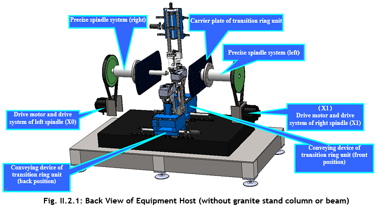
II.2 Precise spindle system: It is mainly composed of spindle box, spindle motor, spindles and spindle bearing. Its startup, shutdown and rotation are controlled by the numerical control system. It makes fiber ring framework winding fiber with the rotation of the spindle, and it is the power output component of the equipment. The spindle is a critical component, and the advantages and disadvantages of its structure have a great impact on the properties of the equipment.
II.3 Full closed-loop tension control system and automatic feeding fiber system (transition ring unit): The equipment is equipped with full closed-loop tension control system which is composed of transition ring (store fiber ring), tension sensor component, servo motor, base, steering guide wheel unit, wobble wheel, etc. The transition ring for storing fiber during winding is placed in the unit so that the automatic interleaving position system can grasp and release the tension control system and automatic feeding fiber system. According to the requirements of symmetrical winding method for fiber ring, the tension control and automatic feeding fiber systems must be constituted by two sets, and thus the equipment is equipped with one pair of the tension control and automatic feeding fiber systems.
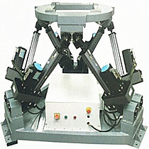
II.4 Automatic interleaving position system: It is comprised of two sets of three-dimensional motion mechanisms. When one transition ring pays off fiber for winding, the other one rotates on the spindle at one side. The alternative interchange of the transition rings achieves many winding methods such as octupole winding method, hexadecapole winding method, crossing winding method, and avoiding crossing winding method.
II.5 Traversing and positioning device of fiber: It is constituted by one set of five-dimensional straight line mechanism. When fiber is at the origin of each layer, its position shows tiny deviation to various extents. The device is designed in the equipment so as to eliminate the tiny deviation. The function of the device is that fiber is made entering the V groove of the two “fiber positioning slot plates” and then positioned, “fiber riding wheel” lifts fiber up, and finally “fiber positioning slot plates” are removed. In this way, fiber is positioned accurately. Meanwhile, “fiber riding wheel” can move in three-dimensional direction to close to the fiber ring as far as possible, so as to reduce the distance from “fiber riding wheel” to the fiber ring; in the case, the overhead fiber has the shortest length, thereby extremely reducing the instability of fiber ring due to vibration caused by too long overhead fiber during winding.
II.6 Precise winding displacement and camera drive unit: It is comprised of one set of three-dimensional motion mechanism (two-dimensional straight line and one-dimensional rotation). The unit has two main functions: firstly, the obstacle of the unit is used for keeping fiber arranging together during winding so as to ensure the whole tightness of fiber arrangement; secondly, the unit is equipped with one set of industrial vision system with special light source. The industrial vision system has large magnification times (i.e., the effective field is small); as a result, the industrial vision system must move synchronously with the traverse shaft if the whole winding process is required to be observed.
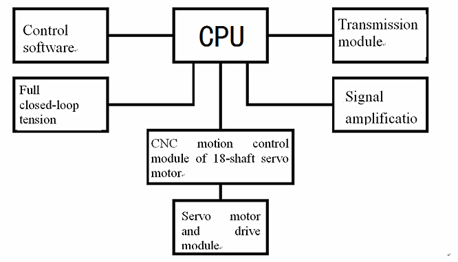
II.7 Control system: It is composed of CNC motion control module of 18-shaft servo motor, full closed-loop tension control system, servo motor and driver module, signal amplification, transmission module, and control software, They are the control centers in which equipment performs sequential control actions and processes.
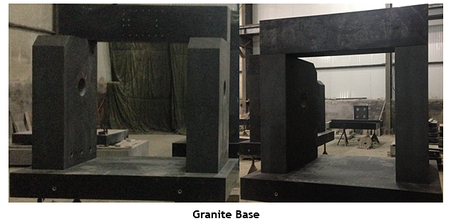
II.1 Base piece (equipment body)
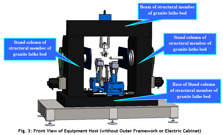
Using high-quality
"Jinan Green" natural granite (moorstone) stone processed by
mechanical processing and manual fine grinding. It has black gloss, precise
structure, even texture, good stability, strong intensity and high hardness.
Besides, it can maintain stability under heavy load and general temperature. The
granite (moorstone) stone through strict physical test and selection has fine
crystal and hard texture; the compressive strength is up to 2290-3750 kg/cm2,
and the hardness reaches Moh's hardness 6-7 grade.
Flatness
tolerance meets GB4987-85 standard: 000 grade=1×(1+d/1000)um, 00
grade=2×(1+d/1000)um (d is diagonal line in mm) (measurement temperature is
20±2℃ generally).
Physical properties: specific gravity: 2970-3070 kg/m2; compressive strength: 245-254 N/m; coefficient of linear expansion: 4.61×10⁻⁶/℃; water absorption: <0.13%; Shore hardness: Hs70 above
The basepiece has advantages of wear resistance, acid and alkali resistant, high corrosion resistance, and no rust. Because granite (moorstone) stone is non-metallic material, the basepiece has neither magnetic response nor plastic deformation. Its hardness is 2-3 times higher than that of cast iron (equivalently HRC>51), and thus the precision can be kept well. The basepiece is superior to the parts with precision measuring basis made of cast iron and steel, and can obtain high and stable precision. It can maintain stability under heavy load and general temperature.
Characters
and advantages of granite (moorstone) slab and platform: through long-term
natural effectiveness, granite has uniform tissue structure and small
coefficient of linear expansion; internal stress disappears completely; it is
not deformed. Therefore, it has high precision, good rigidity, high hardness,
and strong wear resistance. It resists to acid and alkali, and never rusts, and
thus no oil is applied. It is not easy to adhere to mote; it is simple and
convenient for maintenance; its service life is long. No scratch appears. It is
not subject to constant temperature. The measuring precision can be also kept
in normal temperature. It cannot be magnetized. It can move smoothly during
measuring without sluggish
and acerbity.
It cannot be affected by moist.
II.2 Precise spindle system
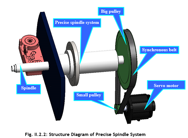
The precise spindle system of the equipment is composed of spindle motor, spindle drive system and spindle unit. It is the key component of the equipment. Compared with the quadrupole symmetrical winding equipment developed previously, the spindle system of this equipment has higher rotation speed, higher rotation precision, and higher structural rigidity and vibration resistance.
The spindle system meets the requirements as follows:
(a) Speed regulation function: In order to adapt the process requirements of different procedures, multiple winding methods and various fiber materials, the spindle can achieve stepless speed regulation in a certain speed regulation range to ensure the rational selection of the rotation speed during winding, thereby obtaining the optimal winding efficiency, winding precision and quality. The index of the speed regulation range is mainly decided by the requirements of various processing technologies on the lowest and highest speeds of the spindle.
(b) The system has higher precision and rigidity, stable transmission, and low noise.
(c) Acceleration time and deceleration time are short and meantime speed regulation is stable. The equipment has the forward and reverse rotation functions; acceleration and deceleration can be controlled automatically during changing direction as required.
(d) The spindle unit shall have a high inherent frequency to meet the requirements of vibration resistance and heat stability.
(e) The equipment has the function of quickly and high precision self-centering locking by using ER32 chuck.
(f) The spindle has enough driving power or output torque to meet the winding requirements in the whole speed range, so as to meet the requirements of the equipment under various winding conditions.
(9) When the spindle stops, it is controlled in a fixed position, which is necessary for the interleaving position of transition rings.
The spindle speed of the equipment is designed in the range of 0-400 rpm (the maximum line speed shall not be higher than 12 m/min during winding). The spindle motor is a standard AC servo motor (Mitsubishi 2 KW AC servo motor). The circle-arc tooth synchronous belt is used for transmission; 5M circle-arc tooth synchronous belt is selected here and also called HTD synchronous belt for transmission; 1:5 synchronous cog belt is used for transmission and the belt width is 38 mm. The diagram of the transmission device is shown below:
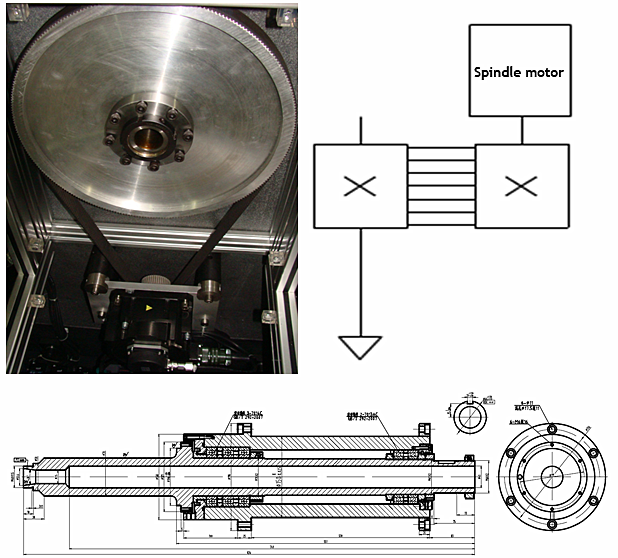
The spindle unit is one of important components and the executive component of the equipment. It is used for making and driving workpiece or transition rings to rotate, sustaining various loads, and completing winding motion. The spindle unit is comprised of transmission component, sealing element, and the like mounted on the spindle by spindle machine. Because the rotation speed of the equipment is required to be stable, the spindle unit shall have good rotation precision, structural rigidity, vibration resistance, heat stability and precision retentivity. There must be automatic clamping device, spindle orientation device, etc., in order to realize the automatic load, unload, and exertion of transition rings on the spindle.
The spindle is a hollow cylindrical component (the through-hole diameter of the spindle is φ40 mm). ER32 chuck often used for CNC machine center is designed at the fitting position of framework tooling, and there is a bore-hole on the front structure of the spindle. ER32 chuck is mounted in the bore-hole and used for fixing the tooling shaft.
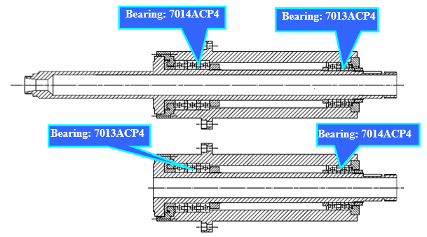
In order to ensure the rigidity of the spindle unit, the front back-up bearing comprises three NSK high-precision spindle angular contact bearings, so that it can bear both radial force and axial force. The bearings are positioned by using bearing end plate respectively. The back back-up bearing also includes one pair of NSK high-precision spindle angular contact bearings which shall be assembled according to certain pretightening force by the bearing plant. For the equipment, the selected front back-up bearing is 3 7014ACP4 and the back back-up bearing is one pair of 7013ACP4. The precision grade is P4 grade. The following requirements shall be met:
a. The coaxiality of the front back-up bearing shall be less than 5 μm;
b. The bearing neck shall be grinded according to the “actual size” of the inner hole of the bearing, and the interference fit shall be 1-5 μm;
c. The coaxiality of the bore-hole and bearing neck shall be 3-5 μm, the taper-face contact area shall not be less than 80%, and the big end of the bore-hole contacts well.
II.3 Full closed-loop tension control system and automatic feeding fiber system (transition ring unit)
It is composed of transition ring (store fiber ring), tension sensor component, servo motor, base, steering guide wheel unit, wobble wheel, etc. The transition ring for storing fiber during winding is placed in the unit so that the automatic interleaving position system can grasp and release the tension control and automatic feeding fiber systems. According to the requirements of symmetrical winding method for fiber ring, the tension control and automatic feeding fiber systems (transition ring unit) must be constituted by two sets, and thus the equipment is equipped with one pair of the tension control and automatic feeding fiber systems. The unit is shown below.
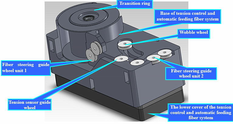
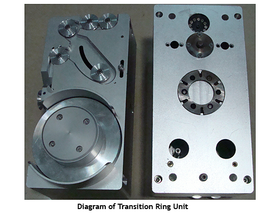
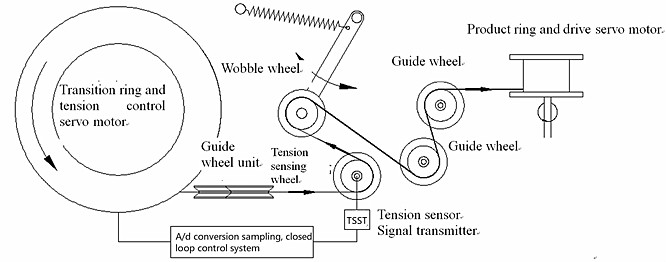
As shown in the Diagram above, the tension control system of the fiber winding machine is composed of several parts: tension sensor and amplification circuit, tension control motor, wobble wheel, preliminary ring support, guide wheel, and A/D sampling and feedback control circuit. During winding, fiber goes out from the preliminary ring support, passes wobble wheel, tension inspection system and pulley, and finally according to the position of the guide wheel, accurately winds around the working ring stand fixed on the spindle.
Structure
Diagram of Tension Control and Automatic Feeding Fiber Systems
When the tension value on fiber is constant, the wobble wheel mainly sustains its own weight, tensile force of the spindle motor in the same winding direction, tensile force of the tension control motor in the same or opposite winding direction and tension of fiber, but it is always in the position in the horizontal direction. If the tension value on fiber varies, the balance on the wobble wheel will be broken. At the moment, the tension sensor inspects the tension change and converts it to the voltage change value. Subsequently, the change value is converted to digital signals through AD sampling circuit, and the signals are transmitted to the main control circuit. Then, the rotation speed of the tension control motor is adjusted by PID algorithm so as to indirectly change the output torque, thereby recovering balance on the wobble wheel. Finally, the wobble wheel turns back to the horizontal position, and the tension value on the fiber is controlled in a stable range.
During winding of fiber, the spindle motor exerts tensile force, fiber passes the fixed pulley. If the wobble wheel cannot be kept at the horizontal position, this means that the tension changes on fiber. If the tension increases, the tension control motor makes the rotation speed fast by feedback algorithm. When the tensile force and the tension decrease, the rotation speed of the tension control motor slows so that the tensile force on the fiber increases to the set value.
Sampling and feedback control circuit. It is used for collecting the output value of the tension sensor and controlling the operation of the tension motor through feedback, thereby realizing the real-time stable control of the tension system.
The motor for tension control must have the advantages of stable torque output under different rotation speeds, small pulsating quantity, fast response time, small moment of inertia, compact structure and simple control mode. AC servo motor can run very stably, and never shows oscillation phenomenon even at low speed. AC servo motor has the function of resonance suppression, but it has insufficient mechanical rigidity. Besides, there is frequency resolution function (FFT) in the system, which can detect the resonance point of the machine and is convenient for system adjustment. AC servo system has favorable acceleration performance and spends only several milliseconds from zero to the rated rotation speed of 3000 RPM, and it can be used for the control occasion of fast startup and shutdown. Therefore, it is ideal that AC servo motor is taken as the tension control motor. Moreover, AC servo motor is used because the spindle motor and sliding motor of the winding subsystem need accurate orientation and stable torque output. Through market survey, we adopt GYS101DC2-T2A from Fuji Electric as the tension control motor. This motor has the following characteristics:
a. The vibration attenuation control function, created by Fuji Electric, can restrain mechanical vibration to the most extent.
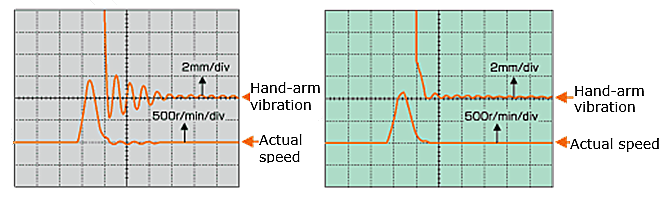
Vibration waveform measured by laser displacement meter
b. The high-resolution encoder with pulse of 131072 is used, which improves the rotation resolution of the servo motor and realizes low-speed stable mechanical operation.
c. The inherent resonance frequency of the machine is analyzed by the debugging software, which can effectively utilize the functions such as vibration reduction control and notch filter.
II.4 Automatic interleaving position system
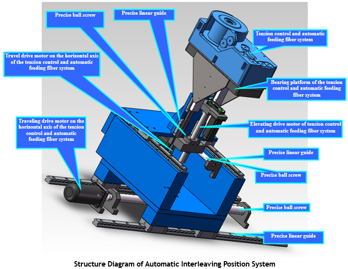
When one transition ring pays off fiber for winding on the platform, the other one rotates on the flying fork plate of the spindle. The alternative interchange of the transition rings achieves many winding methods such as octupole symmetrical winding method, hexadecapole symmetrical winding method, crossing symmetrical winding method, and avoiding crossing symmetrical winding method. These winding methods shall be compatible in the same machine, which is achieved through interleaving position functions of grasping, carrying and accurate positioning of the transition ring unit, and driving of transition rings (demand of tension closed-loop control).
Characteristics of automatic interleaving position system:
Because of the particularity of the symmetrical winding method, there must be two sets of transition ring units; the movement unit matching with the transition ring for interleaving position must be two sets of mutually independent four-dimensional (three-dimensional linear movement + one-dimensional rotational movement) movement mechanisms (in order to distinguish the two sets, we arrange them in front and back positions). The transition ring completes the operation functions such as grasping, carrying, and accurate positioning in a three-dimensional space, and thus the function of meeting three-dimensional linear movement is taken into consideration in the designing process of the system. The drive of the transition ring (demand of tension closed-loop control) is necessary for automatic pay-off and collecting unit to meet tension control. When the tension is larger, the unit will pay off fiber; on the contrary, the unit will collect the released fiber to ensure the stability of tension.
Technical indexes of automatic interleaving position system:
| Technical
Indexes of Automatic Interleaving Position System |
||
| Carrying device |
Unit |
2 sets |
| Number of axes in linear movement |
|
3 |
| Drive motor on X-axis |
W |
400 W AC servo motor |
| Maximum stroke on X-axis |
mm |
550 |
| Travel precision on X-axis |
mm |
0.005 |
| Repeated precision on X-axis |
mm |
0.005 |
| Drive motor on Y-axis |
W |
100 W AC servo motor |
| Maximum stroke on Y-axis |
mm |
180 |
| Travel precision on Y-axis |
mm |
0.005 |
| Repeated precision on Y-axis |
mm |
0.005 |
| Drive motor on Z-axis |
W |
100 W AC servo motor (with brake) |
| Maximum stroke on Z-axis |
mm |
180 |
| Travel precision on Z-axis |
mm |
0.005 |
| Repeated precision on Z-axis |
mm |
0.005 |
| Maximum displacement speed on
X/Y/Z-axis |
mm/s |
120 |
| Drive of transition rings |
|
|
| Drive motor |
set |
100 W AC servo motor |
| Electrical sucker for grasping and
taking |
|
Equipped |
II.5 Traversing and positioning device of fiber
It is composed of one set of five-dimensional straight line mechanism. Its usage is shown below: fiber is made entering the V groove of the two “fiber positioning slot plates” and then positioned, “fiber riding wheel” lifts fiber up, and finally “fiber positioning slot plates” are removed. In this way, fiber is positioned accurately. Meanwhile, “fiber riding wheel” can move in three-dimensional direction to close to the fiber ring as far as possible, so as to reduce the distance from “fiber riding wheel” to the fiber ring, i.e., the length of the overhead fiber, thereby extremely reducing the instability of fiber ring due to vibration caused by too long overhead fiber during winding.

Technical indexes of fiber traversing and positioning device:
| Technical
indexes of Fiber Traversing and Positioning Device |
||
| Carrying device |
Unit |
1 set |
| Number of axes in linear movement |
|
5 |
| Drive motor on X-axis |
W |
400 W AC servo motor |
| Maximum stroke on X-axis |
mm |
550 |
| Travel precision on X-axis |
mm |
0.005 |
| Repeated precision on X-axis |
mm |
0.005 |
| Drive motor on X1-axis |
W |
100 W AC servo motor |
| Maximum stroke on X1-axis |
mm |
120 |
| Travel precision on X1-axis |
mm |
0.005 |
| Repeated precision on X1-axis |
mm |
0.005 |
| Drive motor on Y-axis |
W |
100 W AC servo motor |
| Maximum stroke on Y-axis |
mm |
220 |
| Travel precision on Y-axis |
mm |
0.005 |
| Repeated precision on Y-axis |
mm |
0.005 |
| Drive motor on Z-axis |
W |
100 W AC servo motor (with brake) |
| Maximum stroke on Z-axis |
mm |
220 |
| Travel precision on Z-axis |
mm |
0.005 |
| Repeated precision on Z-axis |
mm |
0.005 |
| Drive motor on Z1-axis |
W |
100 W AC servo motor (with brake) |
| Maximum stroke on Z1-axis |
mm |
220 |
| Travel precision on Z1-axis |
mm |
0.005 |
| Repeated precision on Z1-axis |
mm |
0.005 |
| Maximum displacement speed on
X/X1/Y/Z/Z1-axis |
mm/s |
120 |
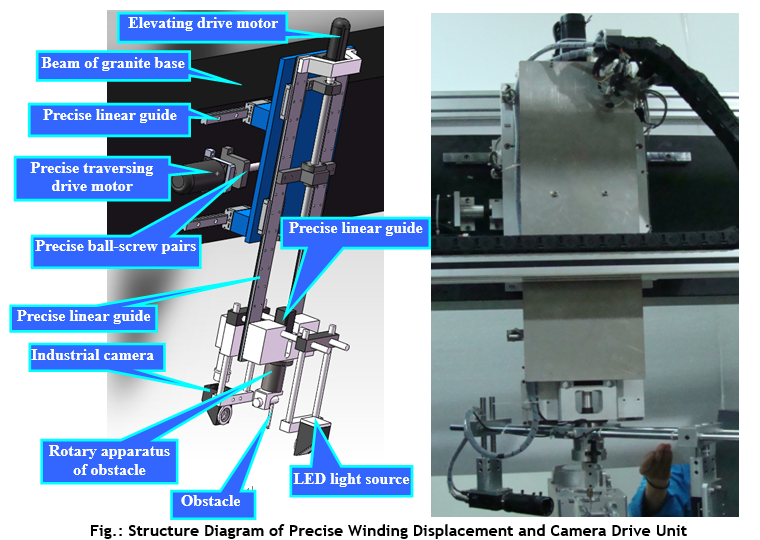
II.6 Precise winding displacement and camera drive unit:
It is comprised of one set of three-dimensional motion mechanism (two-dimensional straight line and one-dimensional rotation). The unit has two main functions: firstly, the obstacle of the unit is used for keeping fiber arranging together during winding so as to ensure the whole tightness of fiber arrangement; secondly, the unit is equipped with one set of industrial vision system with special light source. The magnification of industrial vision system is large (i.e., the effective field of view is small); as a result, the industrial vision system must move synchronously with the traverse shaft if the whole winding process is required to be observed. The unit is shown below.
Technical indexes of precise winding displacement and camera drive unit:
|
Technical
Indexes of Precise Winding Displacement and Camera Drive Unit |
||
| Carrying device |
Unit |
1 set |
| Number of axes in linear movement |
|
3 |
| Drive motor on X-axis |
W |
400 W AC servo motor |
| Maximum stroke on X-axis |
mm |
220 |
| Travel precision on X-axis |
mm |
0.005 |
| Repeated precision on X-axis |
mm |
0.005 |
| Drive motor on Z-axis |
W |
100 W AC servo motor (with brake) |
| Maximum stroke on Z-axis |
mm |
220 |
| Travel precision on Z-axis |
mm |
0.005 |
| Repeated precision on Z-axis |
mm |
0.005 |
| Maximum displacement speed on
X/Z-axis |
mm/s |
120 |
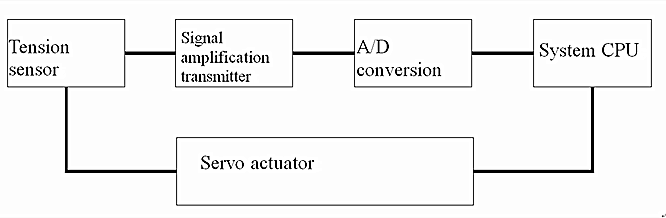
II.7 Control system
The control system is composed of CNC motion control module of 18-shaft servo motor, full closed-loop tension control system, servo motor and drive module, signal amplification, transmission module and control software, which are the control center for the equipment executing sequential control action and finishing the processing. The control system is shown as follows.
The control system can reach the requirements below:
a. In normal operation, the controllable rotation speed of the spindle is 0~40 rpm, and the maximum winding speed is not lower than 10 m/min;
b. Precision of winding turns: the error between the turns of each layer and the set turns shall not be more than 1;
c. It has the precise fiber assistant positioning and traversing device and the location precision is superior to 0.01 mm;
d. The rotational positioning accuracy of the spindle is superior to 1°;
e. The set and control range of tension is 5g~20g, and the control precision of the tension is superior to 1.5 g; the tension is kept stable during startup and shutdown of the equipment, and the fluctuation is not higher than ±2 g;
f. It has a good human-computer interaction function, and the key parameters of the monitoring system can be displayed in real time.
Applications
● Fiber optical Gyroscope
Related Products
© FOGphotonics, inc. | Company | Products | Technoloy | Contact us