


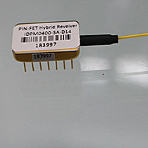
PINFET Optical Receiver for fibre optic gyro systems
Product Features
● InGaAs PIN detector plane structure
● Fixed transimpedance amplifier circuit
● Working wavelength of 1100nm ~ 1650nm
● 14needle shallow cavity dual-in-line package
● With SM or PM fiber coupled,FC/PC FC/APC connector
optional
● High and low temperature storage testing
● Full temperature operating testing
● High Sensitivity PIN-FET Receiver Module(
Transimpedance: 10-1200Kohms, ,dynanmic range: 25dB, package: 14pins/8 pins)
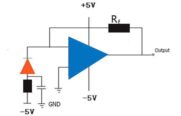
PIN-FET Hybrid Receiver Working Theory
PIN-FET Designed by FOGPhotonics Including two mainly electronic part-byway Detector and operational amplifier circuit(OAC).The Byway detector is PD Which Converts an optical signal into an electrical signal,The OAC is mainly used to amplify the PD converted electrical signals to achieve an ideal output signal.
The schematic diagram of the working Theory is shown in the following figure:
Technical Specification
Specifications @ 25℃ (+/- 5.0 VDC)
| Type |
Bandwidth* (MHz) |
Sensitivity (dBm) |
Transimpedance (Kohms) |
Dynamic range (dB) |
Noise (mV) |
| IDPM0030 |
180 |
-40 |
70 |
25 |
0.1 |
| IDPM0070 |
120 |
-43 |
30 |
25 |
0.1 |
| IDPM0010 |
60 |
-45 |
10 |
25 |
0.1 |
| IDPM0040 |
40 |
-49 |
40 |
25 |
0.1 |
| IDPM0060 |
30 |
-50 |
60 |
25 |
0.2 |
| IDPM0400 |
12 |
-52 |
400 |
25 |
0.3 |
| IDPM0800 |
8 |
-54 |
800 |
25 |
0.5 |
| IDPM1200 |
6 |
-55 |
1200 |
25 |
0.7 |
| IDPM1400 |
4 |
-56 |
1400 |
25 |
0.9 |
NOTE:
From July 2017 FOGPhotonics accept higher bandwidth at 450MHZ( Data rate 622M);900MHZ(Data rate 1.25G);1700MHz(Data rate 2.5G) OEM service.Min qty:10pcs Please contact us for more details: info@fogphotonics.com
Parameter @25℃ (+/- 5.0 VDC)
| Parameter |
Symbol |
Unit |
Min |
Typ |
Max |
Test condition |
| Electrical
Characteristics |
||||||
| Rate |
- |
Mb/s |
2 |
- |
280 |
|
| Transimpedance |
- |
KΩ |
30 |
|
8000 |
|
| Detector dark
current |
Id |
nA |
- |
0.2 |
5 |
|
| Output
impedance |
Ro |
Ω |
- |
50 |
- |
|
| -3dB Bandwidth |
BW |
MHz |
1 |
- |
180 |
|
| Output voltage |
Vout |
mVp-p |
- |
1000 |
1200 |
RL=50Ω |
| Optical
Characteristics |
||||||
| Sensitivity |
S |
dBm |
-56 |
- |
-39 |
NRZ BER=10-9 |
| Sensitivity vs
temperature |
- |
dB |
- |
1 |
1.5 |
20℃~65℃ |
| Overload |
Pin-max |
dBm |
-3 |
- |
|
|
| PIN Responsibility |
R |
A/W |
0.9 |
- |
- |
λ=1310nm,Vr=-5V |
| 0.95 |
- |
- |
λ=1550nm,Vr=-5V |
|||
| Wavelength
range |
λ |
nm |
1100 |
- |
1650 |
|
| +5 V Operating
current |
IOC+5 |
mA |
- |
25 |
35 |
|
| -5 V Operating current |
IOC-5 |
mA |
- |
10 |
15 |
|
Absolute Maximum Ratings
| Parameter |
Symbol |
Unit |
Min |
Max |
| Storage
Temperature Range |
Ts |
℃ |
-40 |
85 |
| Relative
Humidity |
RH |
% |
- |
85 |
| Positive Power
Supply Voltage |
Vcc/Vee |
V |
- |
6 |
| Negative Power
Supply voltage |
Vcc/Vee |
V |
|
-6 |
| Reverse
Detector Bias Voltage |
- |
V |
- |
-15 |
| Forward Current |
If |
mA |
- |
2 |
| Reverse
photoCurrent |
Ir |
mA |
- |
5 |
| Fiber coupled
power |
Pin |
mW |
|
5 |
| Lead Solder
Temperature |
- |
℃ |
- |
260 |
| Lead Soldering
Time |
- |
s |
- |
10 |
*The sensitivity is calculated by using the PINFET transimpedance, the noise voltage (which is RMS of no light input) and the PIN responsivity. And it is at the conditions of room temperature and NRZ code Bit Error Rate better than 10-9.
Recommended Operating Conditions
| Parameter |
Symbol |
Unit |
Min |
Typ |
Max |
| Case
Operating Temperature Range |
Tc |
℃ |
-20 |
|
+70 |
| Operating
Voltage |
VOP |
v |
|
±5 |
|
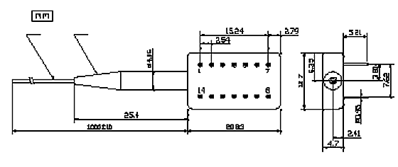
14pin Package
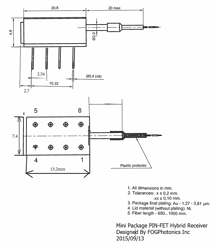
Mini 8pin SK-DIP package
Pin definition
14 pin
|
pin |
function |
pin |
function |
| 1 |
-5V(Bias Voltage) |
8 |
Grounding |
| 2 |
NC |
9 |
NC |
| 3 |
Grounding |
10 |
+5V Power Supply |
| 4 |
-5V Power Supply |
11 |
NC |
| 5 |
Grounding |
12 |
NC |
| 6 |
NC |
13 |
NC |
| 7 |
Signal Output |
14 |
NC |
8 pin
|
Pin |
Definitions |
Pin |
Definitions |
| 1 |
NC |
5 |
-5V Power Supply |
| 2 |
-5V Power Supply |
6 |
Signal Output |
| 3 |
Grounding Power Supply |
7 |
Grounding Signal |
| 4 |
+5V Power Supply |
8 |
Case |
Applications
● Fiber optic gyro system
● Fiber communication system● Fiber sensor system
Ordering information
| IDPM |
xxxx |
xx |
xxx |
| |
1200:1200KΩ |
SP:SM Fiber,FC/PC Connector |
D14:DIP14 |
| |
0800:800KΩ |
SN:SM Fiber,None connector |
D08:DIP8 |
| |
0600:600KΩ |
SA:SM Fiber,FC/APC Connector |
MD08:MINI DIP8 |
| |
0400:400KΩ |
PA:PM Fiber,FC/APC Connector |
|
| |
0060:60KΩ |
PP:PM Fiber,FC/PC Connector |
|
| |
0040:40KΩ |
PN:SM Fiber,None connector |
|
Product Testing Report 
Dimensions of PINFET Optical Receiver 
![]()


Related Products
© FOGphotonics, inc. | Company | Products | Technoloy | Contact us