


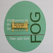
MIOC-13-09-XX-N Multi-function Integrated Optic Chip for Gyroscope
Product Features
● X-Cut, y-propagatingLiNbO3
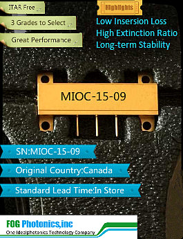
● Very low insertionloss.
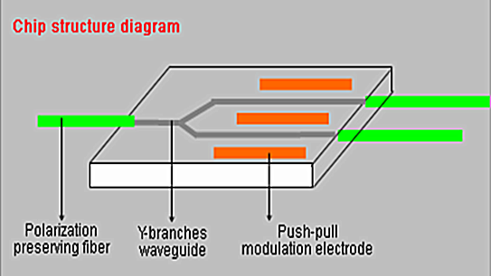
● APE process forwaveguide, works in single polarization
● High extinction ratio
● Fiber is slopingcoupled with waveguide, which deduce optical return far and away
● Push-pull electrodedesign may deduce half wave Voltage
● Small packaging andlightweight
● Excellent long-termstability
Technical Specification
|
Parameter |
Unit |
Values |
| Wavelength |
nm |
1310 |
| Insertion |
dB |
≤4.0 |
| Half
wave Voltage |
V |
≤4.0 |
| Splitting
Beam Ratio |
- |
47/53-53/47 |
| Optical
Return |
dB |
≥50 |
| Polarization
extinction ,chip |
dB |
≥55 |
| Additional
Intensity Modulating |
- |
≤0.2% |
| PM
Pigtail Crosstalk |
dB |
≤-30 |
| Electrode
type |
- |
Push-pull
modulating |
| Bandwidth |
MHz |
≥300 |
| Pigtail
type |
- |
PM |
| Work
temperature |
℃ |
-40~+70 |
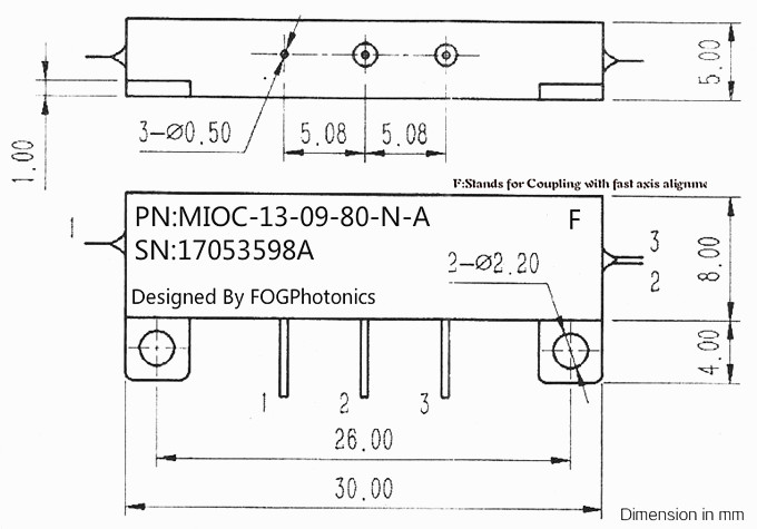
| Packaging
dimensions |
mm |
30X8X5 or 35X10X5 |
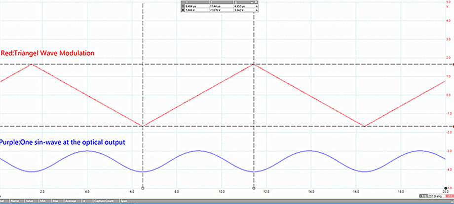
Recommend Modulation Wave(Amplitude Value:≤3.5V)
Applications
● Fiber optic gyroscopes(FOG).
● Fiber optic currentsenser(FOCS)
● Hydrophone and other optic sensitive fields
● Itis for attitude control of movements such as aircrafts, ships, guided missiles,automobiles etc in the fiber gyroscope system, Hydrophone and other opticsensitive fields. Faraday Effect was used to measure current through fibercircuit in the current sensing system.
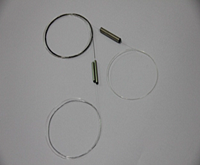
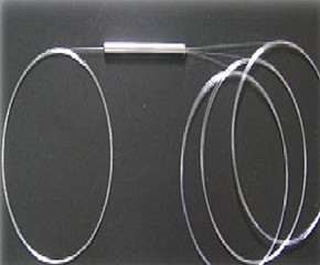
Chip Structure
 |
 |
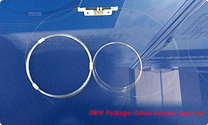
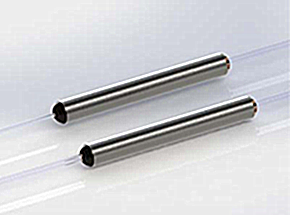
Different packages
New package of Naked ceramic package
 |
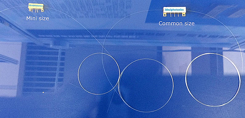 |
Package Common Size
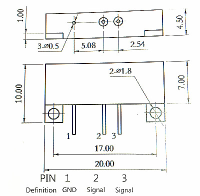
| Items |
Description |
| 1 |
Ground(GND) |
| 2 |
Signal |
| 3 |
Signal |
Package Mini Size
Ordering Information
| Type |
Description |
| MIOC-13-09-09-N |
1310nm integrated optical chips ( Y waveguide)
input/output: 125/250um PM fiber, 1m fiber length, without connector |
| MIOC-13-09-80-N |
1310nm integrated optical chips ( Y
waveguide) input: 125/250um PM fiber,
output with 80/165um PM fiber, 1m fiber length, without connector |
Operation Instructions
g) Avoid stressing to the joint of the fiber connection circuits.
Product Testing Report 

Related Products
© FOGphotonics, inc. | Company | Products | Technoloy | Contact us